- Do you want to know what a transistor is and how it works?
- Are you wondering how transistors are used in electronic circuits?
This article will answer those questions.
I have been studying electronic circuits for about 10 years through my work.
The transistor is one of the very first components you learn about—and for good reason.
It is a fundamental building block used in many different circuits.
In this article, I will explain transistors in a clear and simple way.
What Is a Transistor?
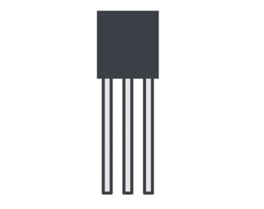
A transistor is an electronic component with the following characteristics:
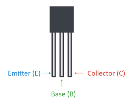
- It consists of three terminals: the collector, emitter, and base.
- It can amplify electric current.
- It can act as a switch, turning current on and off.
In this article, the term “transistor” refers specifically to a bipolar junction transistor (BJT).
Note:
The pin configuration may vary depending on the transistor model.
For example, the 2N3904 (NPN) and 2N3906 (PNP) have pins arranged as E–B–C when viewed from the front, while the Japanese 2SC1815 (NPN) has a different order of E–C–B.
Always check the datasheet to confirm the correct pin layout before wiring.
How Does a Transistor Work?
A transistor operates when a small current flows into its base terminal.
This base current allows a much larger current to flow between the collector and the emitter.
The reason this happens is because applying a base current reduces the “depletion region”,
a barrier that normally prevents current from flowing.
There are two main types of transistors: NPN and PNP.
In this section, we will focus on the NPN transistor, which is the most commonly used type.
NPN Transistor
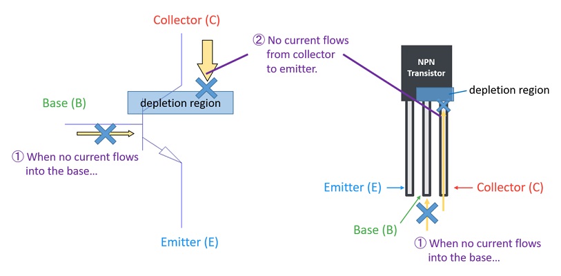
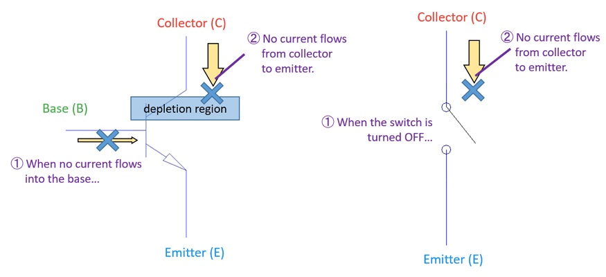
When no current flows into the base terminal,
a depletion region forms between the base and the emitter,
and current cannot flow through the transistor.
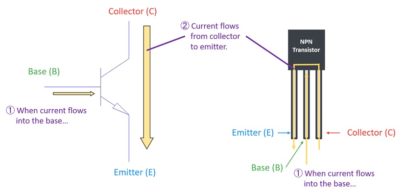
When a base current is applied,
the depletion region becomes very narrow,
allowing current to flow freely from the collector to the emitter.
Thus, by controlling the base current,
the transistor can amplify current or act as a switch to turn current on and off.
Two Main Functions of a Transistor
A transistor has two main functions in electronic circuits:
- It can amplify current.
- It can act as a switch, turning current on and off.
1. Current Amplification
A transistor has a characteristic called current gain (also known as β or hFE).
For example, suppose the current gain is 100.
If you apply 1 mA to the base terminal,
the transistor can allow 100 mA of current to flow from the collector to the emitter.
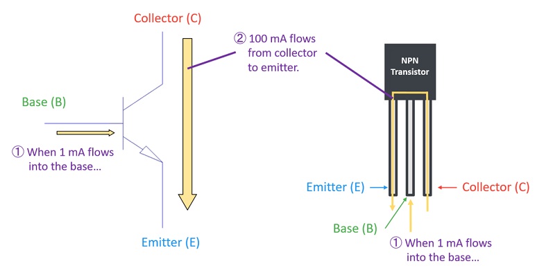
This means:
Base current (1 mA) × Gain (100) = Collector current (100 mA)
Thus, a transistor can amplify a small current at the base into a much larger current through the collector–emitter path.
2. Switching Operation
A transistor can also operate like an electrical switch.
As explained earlier,
when no current flows into the base terminal,
no current flows from the collector to the emitter — this is the OFF state.
When a base current is applied,
current flows freely from the collector to the emitter — this is the ON state.
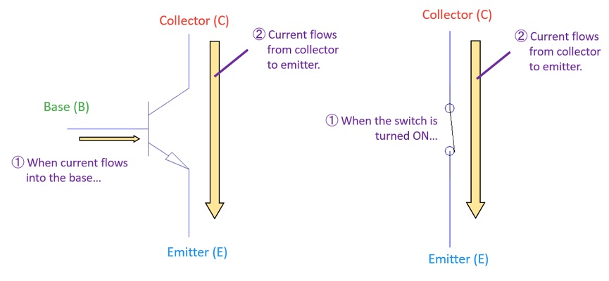
In this way, by controlling the base current,
a transistor can turn the current flow between the collector and emitter on and off,
just like a switch.
Summary
In electronic circuits, a transistor is used mainly for two purposes:
- To amplify current, and
- To act as a switch that turns current on and off.
How to Use a Transistor
Now that you understand that a transistor can amplify current and act as a switch,
let’s look at a simple circuit example where both of these functions are used —
an LED lighting circuit.
Driving an LED with a Transistor
Let’s take a power LED that requires 500 mA to light up as an example.
A microcontroller (CPU) can typically output only a few tens of milliamps,
which is not enough to drive a 500 mA LED directly.
In such cases, a transistor can be used to allow a large current to flow through the LED.
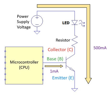
Example Calculation
Suppose we use a transistor with a current gain (β) of 500.
If the CPU outputs 1 mA of current to the base terminal,
then the transistor can allow 500 mA of current to flow
from the collector to the emitter.
That means:
Base current (1 mA) × Gain (500) = Collector current (500 mA)
As a result, the LED receives 500 mA and lights up.
This is an example of using a transistor to amplify current.
Turning the LED On and Off
If you want to make the LED blink instead of staying on,
you can use the transistor’s switching function.
By turning the base current on and off every second from the CPU,
the transistor alternates between the ON and OFF states.
Consequently, the LED will turn on and off every second,
creating a blinking effect.
Summary
By controlling the base current with a microcontroller,
a transistor can be used to:
- Amplify current — to drive high-current components like power LEDs.
- Act as a switch — to turn devices on and off electronically.
Understanding Transistors Through Practice
The best way to understand how a transistor works is to build a simple circuit yourself.
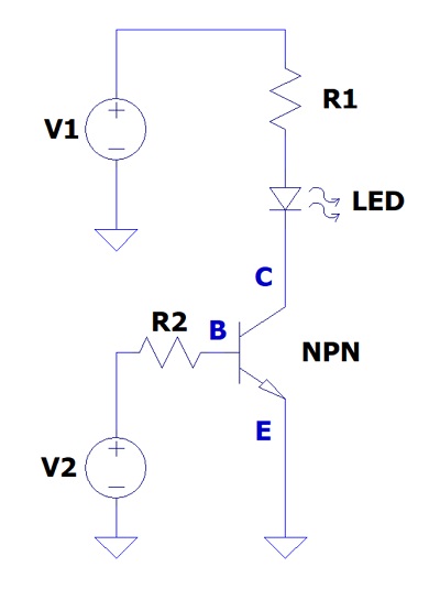
Example Circuit
Below is a basic transistor LED lighting circuit.
By experimenting with this circuit, you can clearly see how the transistor works.
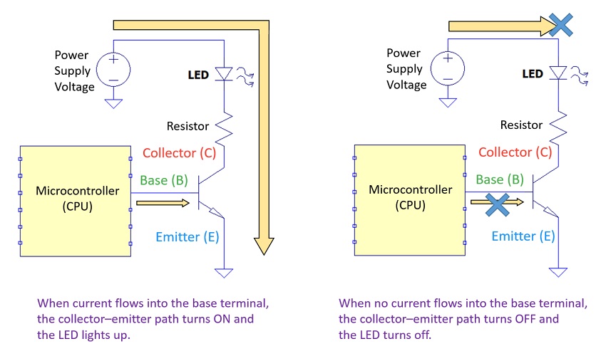
When you apply voltage to the base terminal (B) through a resistor:
→ A small base current flows.
→ The depletion region becomes very narrow.
→ Current flows from the collector (C) to the emitter (E).
→ The LED lights up.
When you do not apply voltage to the base terminal (0 V):
→ No current flows into the base.
→ The depletion region remains wide.
→ No current flows from collector to emitter.
→ The LED stays off.
In this way, you can understand how a transistor operates by observing the LED’s on/off state.
Components You’ll Need
In this way, you can understand how a transistor operates by observing the LED’s on/off state.
- NPN Transistor: 2N3904
-
A classic small-signal transistor, ideal for LED lighting and switching experiments.
It’s one of the most common beginner-friendly transistors used worldwide. - Resistor Set
-
You’ll need resistors from about 330 Ω to 10 kΩ.
For basic experiments, 1/4W resistors are sufficient, but for higher-current circuits, use 1/2W or more. - LED Set
-
LEDs emit light when current flows through them.
Having multiple colors (red, yellow, green, blue, white) helps you experiment easily. - Breadboard (830 holes)
-
A solderless breadboard makes it easy to build and modify circuits.
Ideal for beginners and quick prototyping. - Jumper Wire Set
-
Used to connect components on the breadboard.
Having male–male, male–female, and female–female wires increases flexibility. - USB 5 V Breadboard Power Module
-
Provides a stable 5 V or 3.3 V supply directly to the breadboard.
Convenient for quick experiments. - Digital Multimeter (Tester)
-
Use a multimeter to measure voltage and current to confirm transistor operation.
Start with a simple, affordable model for learning.
Important Notes
Transistor pin layouts vary depending on the model and manufacturer.
Also, the maximum voltage and current ratings differ by product.
Always check the datasheet before connecting components to ensure correct pin assignment and safe operation.
Useful Measurement Tools
When experimenting, you might wonder:
“Is the current really being amplified?” or “Is it switching correctly?”
In such cases, these instruments are helpful:
- To easily check voltage and current: → Digital Multimeter
- To observe signal waveforms: → Oscilloscope
- To power your circuit safely with a stable source: → DC Power Supply
Conclusion
In this article, we learned how a transistor works and what it does.
It’s one of the most important components in electronics—used everywhere as an amplifier or a switch.
Once you understand the basics, you can start applying transistors to your own circuits and electronic projects.
Related Articles
Bonus: Digital Logic Gates Can Be Represented with Transistors
In digital circuits, you may have seen MIL symbols (logic gate symbols) like the ones below.
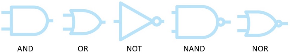
These MIL symbols can actually be represented using transistors and resistors.
Let’s take the NAND gate as an example.
How the NAND Gate Works
The operation of a NAND gate is as follows:
| A | B | Y |
| 0 | 0 | 1 |
| 0 | 1 | 1 |
| 1 | 0 | 1 |
| 1 | 1 | 0 |
Only when both A and B are “1”, the output Y becomes “0.”

NAND Gate Implemented with Transistors
When we represent a NAND circuit using transistors and resistors,
it looks like this:
The following waveforms show the voltage signals in this circuit:
- V(a) – Input A (blue line)
- V(b) – Input B (red line)
- V(y) – Output Y (green line)
These waveforms were obtained by simulating the NAND circuit
using the LTspice electronic circuit simulator.
When 5 V is treated as logic “1,”
you can see that Y is “0” only when both A and B are “1,”
just as shown in the truth table above.
This behavior is achieved because the transistors are used
like switches that turn ON and OFF.
Thus, digital logic symbols (MIL symbols) can be expressed
using transistors and resistors.