
- I want to understand the circuit symbols of transistors.
- What does the arrow in the transistor symbol mean?
- I sometimes forget which way the arrow points — is there an easy way to remember it?
- Why are transistors labeled with the letter “Q” in circuit diagrams?
This article answers these common questions.
I’ve been studying electronic circuits professionally for about 10 years.
When you look at a circuit diagram, do you tend to glance over the transistor symbols without really thinking about them?
In this article, I’ll explain the transistor symbols, the meaning of the arrow direction, and why the circuit label “Q” is used.
Transistor Circuit Symbols and Types
Transistor Symbols
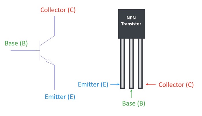
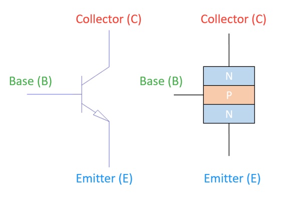
The circuit symbols of transistors are shown below.
NPN Transistor
PNP Transistor
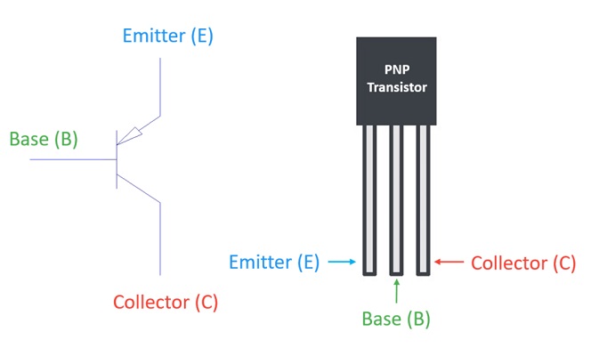
A transistor has three terminals — E (Emitter), B (Base), and C (Collector) — and its circuit symbol reflects this structure.
Note:
The pin configuration may vary depending on the transistor model.
For example, the 2N3904 (NPN) and 2N3906 (PNP) have pins arranged as E–B–C when viewed from the front, while the Japanese 2SC1815 (NPN) has a different order of E–C–B.
Always check the datasheet to confirm the correct pin layout before wiring.
Transistor Types and Part Numbers
There are two main types of transistors: NPN and PNP.
In the past, Japan’s JIS standard classified transistors by their part number prefixes, which indicated their intended applications.
For example, a transistor beginning with 2SA was a “PNP transistor for high-frequency use.”
2SA: PNP transistor (high-frequency use)
2SB: PNP transistor (low-frequency use)
2SC: NPN transistor (high-frequency use)
2SD: NPN transistor (low-frequency use)
This JIS classification system has already been discontinued.
For instance, the well-known 2SC1815 transistor is classified as an NPN transistor for low-frequency applications.
Today, you should not rely on the part number alone to determine a transistor’s type or purpose.
That’s because different semiconductor manufacturers may use their own naming conventions.
Always check the transistor’s datasheet to verify its characteristics.
Meaning of the Arrow in Transistor Symbols
The arrow in a transistor symbol indicates the direction of the base current.
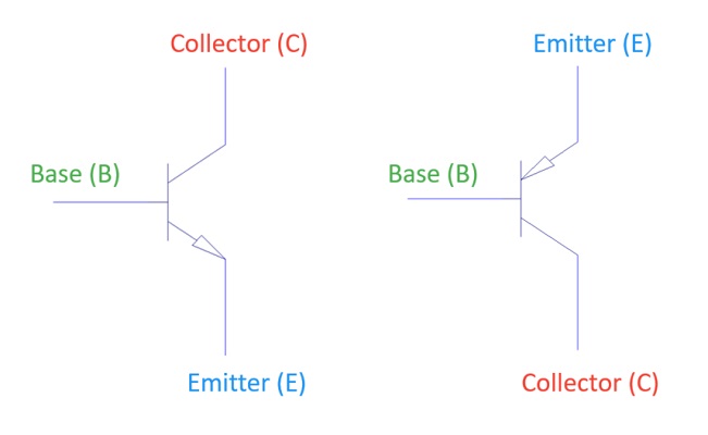
For an NPN transistor, the arrow points from the base (B) to the emitter (E).
This means that current flows from the base terminal to the emitter terminal.
For a PNP transistor, the arrow points from the emitter (E) to the base (B).
In other words, current flows from the emitter terminal to the base terminal.
As an additional note, a small change in the base current allows control of a much larger current between the collector and emitter.
In an NPN transistor, the base current controls the larger current flowing from collector (C) to emitter (E).
In a PNP transistor, the base current controls the larger current flowing from emitter (E) to collector (C).
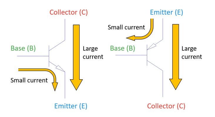
This is the basic amplification principle of a transistor.
How to Remember the Arrow Direction
A simple way to remember the arrow direction is to think of it as P → N.
The transistor symbol and its internal structure are shown below.
NPN Transistor
PNP Transistor
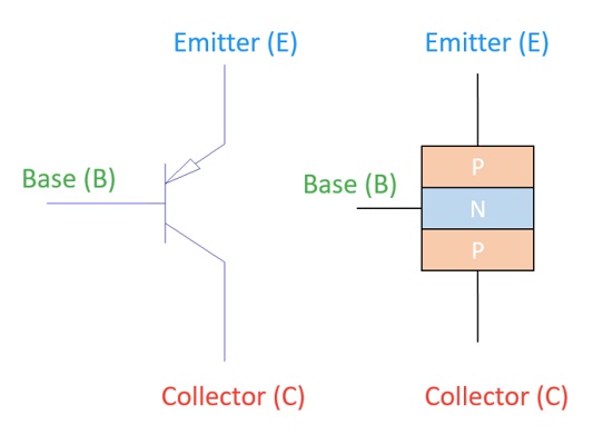
In these structures, the letters “P” and “N” represent Positive and Negative.
P: Positive = + (plus)
N: Negative = − (minus)
Electric current flows from positive (P) to negative (N).
In an NPN transistor, current flows from the base (P) to the emitter (N).
Therefore, the arrow direction is from base (P) to emitter (N).
In a PNP transistor, current flows from the emitter (P) to the base (N).
Therefore, the arrow direction is from emitter (P) to base (N).
In summary, you can remember it simply as P → N.
Why Transistors Are Labeled with “Q” in Circuit Diagrams
The circuit symbol letter “Q” used for transistors comes from the word Quartz.
Before transistors were invented, early radio receivers used crystal detectors made from quartz to rectify radio signals.
Since these devices were based on crystals, the letter “C” (from “Crystal”) would have been a logical choice — but it was already used for capacitors in circuit diagrams.
To avoid confusion, engineers used the letter “Q” (the next letter in “Quartz”) to represent crystal-based devices, and this convention was later inherited by transistors.
In modern circuit diagrams, you may also see transistors labeled as “Tr” to make the schematic easier to read.
However, the use of “Q” is still very common today, so it’s good to be familiar with both.
Let’s Try It Yourself!
To fully understand the meaning of the arrow in a transistor symbol,
The best way is to build a circuit where you can actually observe the direction of current flow.
Example Circuit
This is an LED lighting circuit using an NPN transistor.
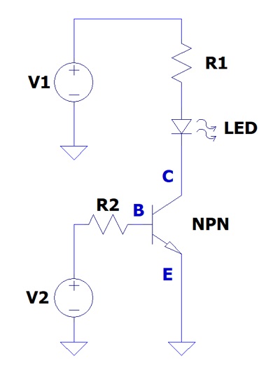
In this circuit, you can actually see that the current flows in the direction of the arrow.
When you apply voltage to the base terminal (B) through a resistor:
→ A small base current flows.
→ The transistor switches to the conduction state.
→ Current flows from the collector (C) to the emitter (E).
→ The LED lights up.
When no voltage is applied to the base terminal (0 V):
→ No base current flows.
→ The transistor remains in the cutoff state.
→ No current flows from collector to emitter.
→ The LED stays off.
In this way, you can confirm through an actual circuit that the arrow direction = current flow direction.
Components You’ll Need
Here are the components you’ll need to build a simple LED circuit using an NPN transistor on a breadboard.
- NPN Transistor: 2N3904
-
A classic small-signal transistor, perfect for checking the arrow direction (current flow) in practice.
You can also observe its ON/OFF switching behavior. - Resistor Set
-
Used for the LED and to adjust the base current. A range of 330 Ω–10 kΩ will be sufficient.
1/4 W resistors are fine for basic experiments, but for higher-current circuits, use 1/2 W or more for safety. - LED Set
-
LEDs allow you to visually confirm whether current is flowing.
It’s convenient to have multiple colors such as red, green, and blue. - Breadboard (830 holes)
-
A solderless breadboard lets you build and modify circuits easily without soldering.
- Jumper Wire Set
-
Jumper wires are used to connect components on the breadboard.
- USB 5 V Breadboard Power Module
-
Provides a 5 V supply directly to the breadboard. Perfect for safe and convenient experiments.
- Digital Multimeter (Tester)
-
Use a multimeter to measure the base current and emitter voltage to verify the actual direction of current flow.
Important Notes
Transistor pin layouts vary depending on the model and manufacturer.
Also, the maximum voltage and current ratings differ by product.
Always check the datasheet before connecting components to ensure correct pin assignment and safe operation.
Useful Measurement Tools
To better understand the concept of “arrow = current direction,” these tools are helpful:
- To easily check voltage and current: → Digital Multimeter
- To observe signal waveforms: → Oscilloscope
- To power your circuit safely with a stable source: → DC Power Supply
Summary
In this article, we’ve learned about the circuit symbols of transistors.
Have you ever taken the time to think carefully about what these symbols really mean?
For an NPN transistor, the arrow points outward, while for a PNP transistor, the arrow points inward — indicating different directions of current flow.
By understanding these symbols, you’ll find it much easier to imagine how a transistor operates when reading a circuit diagram.
Related Articles
Bonus: Tips for Visualizing Transistor Operation
When you look at a transistor symbol in a circuit diagram, first pay attention to the arrow direction.
Tips for remembering:
• NPN = arrow points outward (leaving the emitter)
→ When current flows from base to emitter, the transistor turns ON.
• PNP = arrow points inward (entering the emitter)
→ When current flows from emitter to base, the transistor turns ON.
NPN Example
Current flows from base to emitter.
→ The transistor conducts.
→ Current flows from collector to emitter.
PNP Example
Current flows from emitter to base in the opposite direction.
→ The transistor conducts.
→ Current flows from emitter to collector.
Mini Exercise: Quick Check from Circuit Diagrams
- Which way is the arrow pointing? (Outward = NPN / Inward = PNP)
- Which direction does the base current flow? (NPN = B→E / PNP = E→B)
- Which way does the main current flow? (NPN = C→E / PNP = E→C)