- Want to understand what transistor hFE means?
- Wondering how to measure or calculate transistor hFE?
- Curious why the hFE value varies between transistors?
You’ve come to the right place.
I’ve been studying and working with electronic circuits for about ten years.
When I was a beginner, I didn’t really understand what transistor hFE was either —
but now I do.
By the end of this article, you’ll understand what transistor hFE (also called β) means
and how to find it in a datasheet.
It only takes about three minutes to read — so let’s get started!
What Is Transistor hFE?
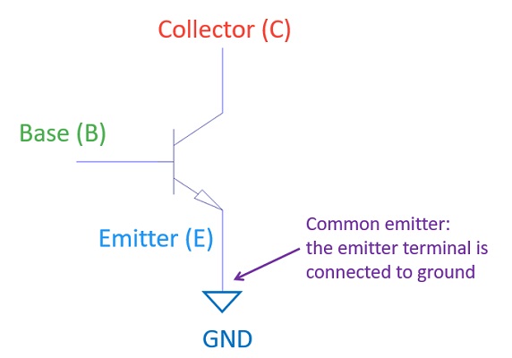
Transistor hFE is the current gain of a transistor when it is connected in a common-emitter configuration.
Transistors have four parameters called h-parameters that describe their electrical characteristics:
- hi – Input impedance
- hr – Voltage feedback ratio
- hf – Current gain
- ho – Output admittance
Among these four, hf represents the current gain.
The “e” in hFE stands for emitter, indicating that this parameter is measured in the common-emitter (CE) configuration.
So, hFE literally means the current gain (hf) when the transistor’s emitter terminal is connected to ground—that is, in a common-emitter circuit.
How to Calculate and Measure Transistor hFE
The hFE of a transistor can be found as the ratio between the collector current (IC) and the base current (IB):
hFE = IC / IB
To measure these currents, you can use a circuit like the one shown below.
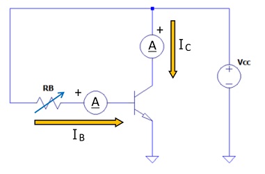
Apply a supply voltage Vcc, then vary the base resistor RB to change the base current IB,
and measure both IB and IC for each setting.
Using the measured values, you can calculate the transistor’s hFE using:
hFE = IC / IB
For example, if you set Vcc = 6 V and vary RB between 200 Ω and 1000 Ω,
you may get the following results:
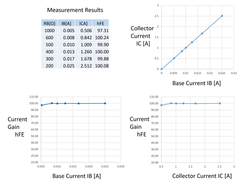
You can see that IC is proportional to IB, and the ratio gives hFE ≈ 100.
FAQ
Understanding Variations in Transistor hFE — Temperature Characteristics and Device Ranking
hFE–IC Characteristics
As seen in the previous measurement example, transistor datasheets include a graph called the hFE–IC characteristics,
which shows how the current gain (hFE) changes as the collector current (IC) varies.
In the simple experiment we performed earlier, hFE remained constant at around 100,
meaning IC increased proportionally with IB.
Let’s now take a look at the datasheet of the 2N3904, one of the most common NPN transistors used worldwide.
2N3904 hFE–IC Characteristics
(excerpted from a Fairchild Semiconductor datasheet).
From the graph, you can see that hFE remains roughly constant at low collector currents.
However, once IC exceeds around 30 mA, the hFE value starts to drop.
This happens because the collector current cannot increase indefinitely —
every transistor has physical and thermal limits.
For example, the collector current IC is supplied by the power source,
so it cannot exceed the power supply’s current capability.
In addition, the transistor itself has a maximum rated collector current beyond which it cannot operate safely.
Since hFE = IC / IB, when IB increases proportionally, IC also increases —
and hFE stays constant.
But when IC no longer increases with IB, the hFE value drops.
From practical experience, when designing amplifier circuits with small-signal transistors like the 2N3904,
keeping IC below about 20 mA allows you to assume a nearly constant hFE value.
Why hFE Varies: Temperature and Manufacturing Differences
1. Temperature Dependence
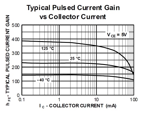
Let’s look at the hFE–IC characteristics again — this time focusing on how hFE changes with temperature.
— same graph as above, excerpted from the Fairchild Semiconductor datasheet.
In this datasheet graph, both the horizontal and vertical axes are logarithmic,
so it’s difficult to read exact values.
However, we can estimate the typical hFE values at different ambient temperatures (Ta) as follows:
| Ambient Temperature (Ta) | Typical hFE (approx.) |
|---|---|
| 125 °C | ≈ 370 |
| 25 °C | ≈ 220 |
| −40 °C | ≈ 150 |
These values show that the transistor’s current gain (hFE) increases as the temperature rises.
At higher temperatures, free electrons inside the transistor move more easily,
which enhances current amplification.
Therefore, when using transistors in environments with large temperature variations,
it’s important to design circuits that can tolerate this change in hFE.
For example, a circuit that works fine at room temperature (25 °C)
might fail to operate on a cold day if hFE decreases too much at low temperatures.
2. Device-to-Device Variations (hFE Classification / Rank)
Each transistor, even of the same model number, exhibits some variation in hFE due to manufacturing tolerances and process differences.
To manage these variations, some transistor families — especially older or European types such as the BC547 series —
classify devices into gain groups or ranks, often referred to as hFE classifications.
For example, according to the Fairchild Semiconductor datasheet,
the BC547 series is divided into three gain ranks:
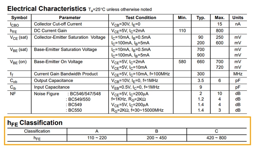
(Excerpted from the Fairchild Semiconductor datasheet.)
| Classification (Rank) | Typical hFE Range |
|---|---|
| A | 110 – 220 |
| B | 200 – 450 |
| C | 420 – 800 |
This system allows engineers to select a transistor with a current gain (hFE) suitable for their circuit design.
For instance, if you need a device with hFE ≈ 100, you can choose the A rank transistor.
However, in most modern American transistors such as the 2N3904,
gain ranking is not commonly used.
Instead, datasheets typically specify a wide hFE range (for example, 100 – 300) that covers all production variations.
The absence of ranking simplifies inventory management, since all units meet general-purpose design requirements.
FAQ
Let’s Try Measuring It Yourself!
By actually measuring the current gain (hFE) of a transistor,
you can experience the differences and variations between the datasheet values and real-world components.
Example Circuit
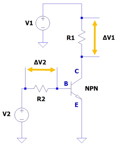
This is a simple circuit for measuring the current gain of a transistor.
The key idea is to calculate the current by measuring the voltage drops across two resistors.
- ΔV1: Voltage drop across the collector resistor R1
- ΔV2: Voltage drop across the base resistor R2
Since the current gain is defined as:
hFE = IC / IB
we can find each current as:
IC = ΔV1 / R1
IB = ΔV2 / R2
So, by simply measuring ΔV₁ and ΔV₂ with a multimeter,
you can determine IC and IB, and then calculate hFE.
If your measured value differs from the datasheet,
don’t worry — this is due to the natural device-to-device variation explained earlier.
As long as your measured hFE falls within the datasheet range, it’s perfectly normal.
Why Measure the Voltage Drop Instead of Current Directly?
Measuring small currents directly can lead to large errors.
By measuring the voltage drop across a resistor, you minimize the measurement error.
For example, if the input impedance of your digital multimeter (e.g., AstroAI Digital Multimeter) is 10 MΩ,
and the base resistor R₂ is 100 kΩ, the measurement error is:
100kΩ / 10MΩ = 1 / 100 = 1%
That’s small enough to ensure accurate results —
which is why we measure the voltage drops across resistors instead of current directly.
Parts You’ll Need
- NPN Transistor: 2N3904
-
A classic small-signal transistor ideal for measuring current gain.
It’s one of the most widely used NPN transistors in the world — perfect for beginners. - Resistor Set
-
These values allow you to build the measurement circuit easily.
For basic experiments, 1/4 W resistors are enough,
but for higher-current tests, 1/2 W or larger is safer. - Breadboard (830 tie points)
-
No soldering required — just insert components and experiment.
Perfect for learning and modifying circuits quickly. - Jumper Wire Set
-
Used for connecting components on the breadboard.
Having male–male, male–female, and female–female types increases flexibility. - USB 5V Breadboard Power Module
-
Provides a stable 5V or 3.3V power source directly to the breadboard.
Convenient for quick experiments.
Important Notes
Transistor pin layouts vary depending on the model and manufacturer.
Also, the maximum voltage and current ratings differ by product.
Always check the datasheet before connecting components to ensure correct pin assignment and safe operation.
Useful Measuring Tools
- Digital Multimeter (Tester)
-
Many multimeters have an hFE test function — you simply insert the transistor to read its gain.
Even if your meter doesn’t have this function,
you can still calculate hFE by measuring ΔV₁ and ΔV₂ as explained above. - Transistor Tester
-
A handy tool that automatically measures hFE when you insert a transistor.
Great for comparing multiple transistors or checking unknown ones. - DC Regulated Power Supply
-
Compared with the USB 5V module, it allows more flexibility in voltage settings —
e.g., 9V, 12V, or 15V.
You can test how hFE changes under different supply voltages.
Summary
In this article, we explored the concept of transistor hFE,
one of the most important parameters that defines how a transistor amplifies current.
Transistors are used in a wide variety of electronic circuits,
so understanding their current gain (hFE) is essential for accurate circuit design and analysis.
By understanding the meaning of hFE and the causes of its variation,
you can handle transistors more confidently and design more reliable circuits.