- What is a transistor constant current circuit?
- How does a transistor constant current circuit work?
- How can I build an LED constant current circuit using a transistor?
This article will answer these questions.
I have about 10 years of experience in electronic circuit design.
In this guide, we’ll explore the transistor constant current source circuit in detail.
Based on my practical experience, I’ll explain the circuits that are most commonly used in real designs.
It only takes about five minutes to read — let’s get started.
What Is a Transistor Constant Current Circuit?
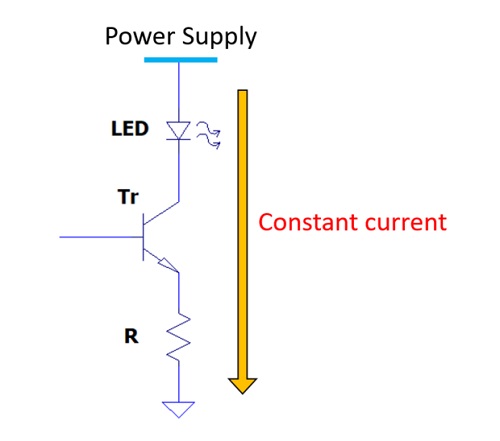
A transistor constant current circuit, as the name suggests, is a circuit that uses a transistor to maintain a steady current flow.
We’ll discuss the working principle and design methods later, but first—why do we even need to keep the current constant?
One common reason is to stabilize the brightness of LEDs or light bulbs.
When you turn on the lights at home, you wouldn’t want them to flicker or vary in brightness—it would be distracting.
Another reason is to obtain accurate readings from sensors.
For example, when measuring temperature, a sensor called a “resistance temperature detector (RTD)” is often used.
This sensor changes its resistance depending on the temperature.
| Temperature | Resistance |
| 50℃ | 119.40Ω |
| 25℃ | 109.73Ω |
| 0℃ | 100.00Ω |
| -25℃ | 90.19Ω |
According to Ohm’s law:
Voltage [V] = Resistance [Ω] × Current [A]
This means that if you pass a constant current through the RTD, any change in resistance directly becomes a change in voltage.
For example, if the constant current is set to 1 mA:
| Voltage | Resistance | Current |
| 119.40 mV | 119.40 Ω | 1 mA |
| 109.73 mV | 109.73 Ω | 1 mA |
| 100.00 mV | 100.00 Ω | 1 mA |
| 90.19 mV | 90.19 Ω | 1 mA |
The CPU (or microcontroller) reads the voltage change—not the current—through an analog-to-digital (AD) converter.
Therefore, to ensure the sensor’s voltage output accurately represents its measured value, the current must be kept constant.

It’s not just a constant current circuit—it’s essentially a current source.
The reason is explained in detail in the following article:
Reference: Transistor Equivalent Circuit Explained – Small-Signal and Amplifier Models
Principle of the Transistor Constant Current Circuit
In a transistor constant current circuit, you can create various types of constant current sources by combining resistors, transistors, and Zener diodes.
However, when it comes to understanding how these circuits work, there is only one essential principle.
That principle is to apply a constant voltage across a resistor.
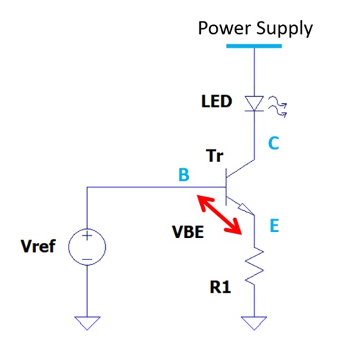
Focus on resistor R1 and the voltage applied across it.
The voltage across R1 is Vref − VBE.
*Vref* is a reference voltage — it can be 12 V, 5 V, 3.3 V, or even 1.2 V, depending on the circuit.
According to Ohm’s law:
Current through R1 = Voltage across R1 / Resistance of R1
For example:
R1 = 1 kΩ
Vref = 5 V
VBE = 0.7 V
Then the current through R1 is:
(Vref − VBE) / R1 = (5 V − 0.7 V) / 1 kΩ = 4.3 V / 1 kΩ = 4.3 mA
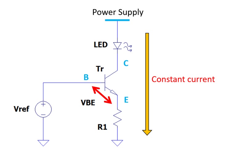
This is the constant current — it remains stable at 4.3 mA regardless of minor changes in supply voltage or load.
By applying a fixed voltage (Vref − VBE) across the resistor R1, we generate a steady current.
In other words, the key question is:
How can we apply a constant voltage to resistor R1?
This is the most important point when designing a constant current circuit.
To achieve it, components like transistors and Zener diodes are commonly used.
In this article, we’ll focus on the most practical configuration — a combination of a resistor, transistor, and Zener diode.
Let’s look at how this combination forms a reliable constant current source.
Designing an LED Constant Current Circuit with a Transistor
How to Design an LED Constant Current Circuit Using a Resistor, Transistor, and Zener Diode
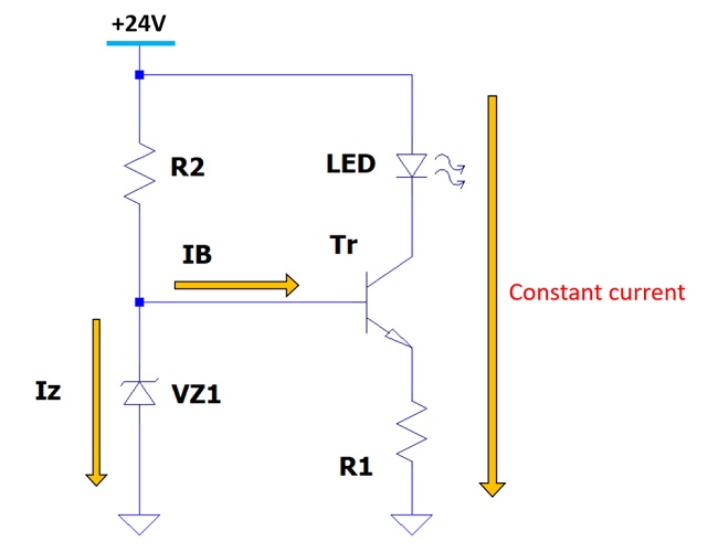
This circuit generates a fixed voltage across the resistor using a Zener diode and a transistor.
The circuit diagram is shown below.
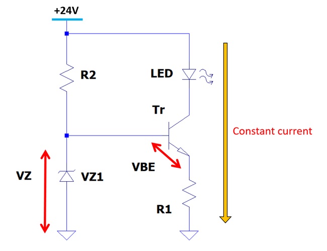
We’ll design the circuit to provide a constant current of 20 mA through the LED. In other words, 20 mA will also flow through resistor R1.
The Zener diode VZ1 used here is Rohm’s UDZV15B.
Electrical characteristics (Ta = 25℃)
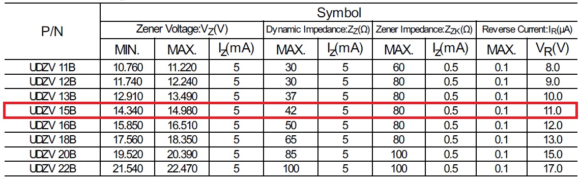
From this, the voltage across resistor R1 is calculated as:
VR1 = VZ − VBE = 14.34 V − 0.7 V = 13.64 V
This fixed voltage (using the minimum Zener voltage) is applied across R1.
To supply 20 mA to the LED, we calculate the value of R1.
Calculating Resistor R1
Using Ohm’s law:
R1 = Voltage across R1 / Constant current = (VZ − VBE) / I = 13.64 V / 20 mA = 682 Ω ≈ 680 Ω
Next, we’ll calculate the value of resistor R2.
Calculating Resistor R2
According to Ohm’s law:
R2 = Voltage across R2 / Current through R2
We’ll determine both the voltage across R2 and the current flowing through it.
The voltage across R2 is:
24 V (supply voltage) − 14.34 V (Zener voltage) = 9.66 V
The current through R2 equals the sum of the Zener current (IZ) and the transistor base current (IB).
From the datasheet, the Zener current IZ is 5.0 mA.
If the transistor has an hFE of 100, then the base current IB is:
IB = Constant current / hFE = 20 mA / 100 = 0.2 mA
Thus, the current through R2 is:
IR2 = IZ + IB = 5.0 mA + 0.2 mA = 5.2 mA
Therefore, the value of R2 is:
R2 = 9.66 V / 5.2 mA = 1.86 kΩ ≈ 1.8 kΩ
Now we’ve successfully designed a constant current circuit using a resistor, transistor, and Zener diode.
Next, let’s check the actual operation using circuit simulation.
Simulation Result of the LED Constant Current Circuit
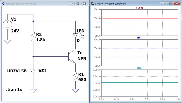
Current waveform of R2:
I(R2) signal (red line)
Current waveform of R1:
I(R1) signal (blue line)
Current waveform of LED:
I(led) signal (green line)
The simulation shows the following current waveforms:
LED: 20 mA
R1: 20 mA
R2: 5.2 mA
The results match the theoretical calculations almost exactly, confirming that the design works properly.

No, you can’t simply replace it.
The transistor and the MOSFET operate on completely different principles.
Even if the LED lights up by chance, that doesn’t mean it’s properly designed.
It’s not a correct design, so such replacement is not recommended.

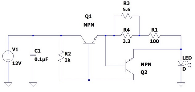
The basic principle is the same. If we simplify the circuit, it looks like the following.
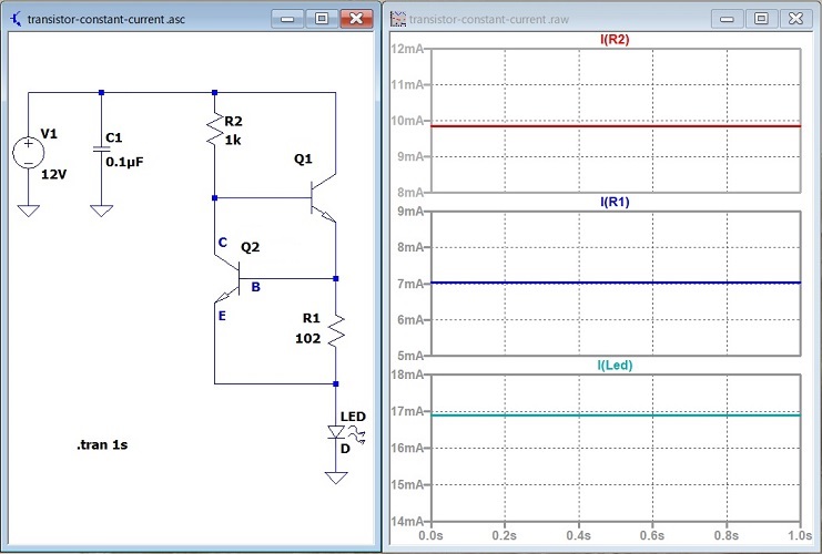
Current waveform of R2:
I(R2) signal (red line)
Current waveform of R1:
I(R1) signal (blue line)
Current waveform of LED:
I(led) signal (green line)
Resistor R1 represents the combined resistance of R1, R3, and R4 from the original circuit.
If we define the parallel combination of resistors R3 and R4 as R34,
1/R34 = 1/R3 + 1/R4
R34 = (R3 × R4) / (R3 + R4) ≈ 2 Ω
R1 = R34 + original R1 = 2 Ω + 100 Ω = 102 Ω
Thus, the result is as follows.
In short, transistor Q2 applies a constant voltage (base-emitter voltage VBE ≈ 0.7 V) across resistor R1, generating a constant current.
Current through R1 = VBE / R1 = 0.7 V / 102 Ω = 6.9 mA ≈ 7 mA
This matches the simulation results almost exactly.
However, since the LED is connected on the ground side,
Current through the LED is the sum of the current through resistor R1 and the current through resistor R2.
The current through resistor R2 remains almost constant.
The sum of the transistor’s collector–emitter voltage VCE and the LED’s forward voltage VF is about 2 V, so:
Voltage across R2 (V2) = V1 − (VCE + VF) = 12 V − 2 V = 10 V
Current through R2 = V2 / R2 = 10 V / 1 kΩ = 10 mA
Therefore,
LED current
= Current through R1 + Current through R2
= 7 mA + 10 mA
= 17 mA
This also matches the simulation results very closely.
As an additional note, if you replace R1 with a variable resistor, you can adjust the LED current.
When R1 is approximately 100 Ω, reducing it to half (50 Ω) doubles the current.
R1: 100 Ω → 7 mA
R1: 50 Ω → 14 mA
Since the current through R2 stays constant at 10 mA,
the total LED current becomes 14 mA + 10 mA = 24 mA.
In this way, the LED current can be adjusted simply by changing the resistance of R1.
Constant Current Circuit Using an Op-Amp and Transistor
The constant current circuit using an op-amp and a transistor is shown below.
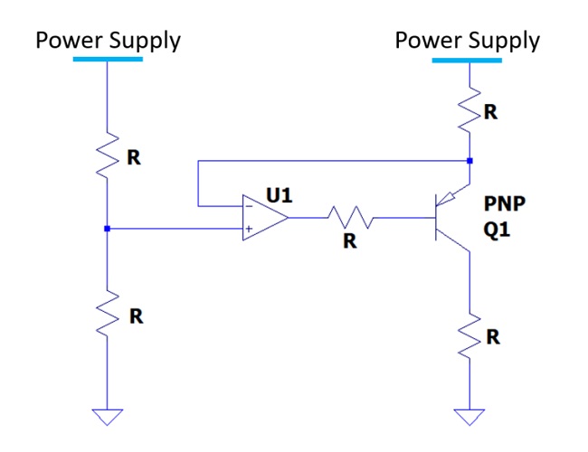
Although this circuit includes an op-amp in addition to a transistor, the essential principle remains the same.
The key idea is how to apply a constant voltage across a resistor.
For a detailed explanation of constant current circuits using an op-amp and transistor, please refer to the following article.
Reference: Op-Amp Constant Current Circuit – Driving LEDs, High-Current FETs, and Oscillation Examples (Coming soon)
Let’s Try It Out!
Let’s actually build the circuit and light up the LED!
Components You’ll Need
Here are the parts required to build a constant current circuit using a transistor and LED.
- NPN Transistor 2N3904
-
A standard small-signal transistor, ideal for experimenting with LED constant current circuits.
Highly recommended for beginners building their first transistor circuit. - Zener Diode Set
-
Used to maintain a stable base voltage.
Recommended for generating a constant reference voltage in your circuit. - Zener Diode UDZV Series
-
If you’d like to use the UDZV15B introduced earlier,
it’s available as an SMD (surface-mount) component and can be obtained easily. - Resistor Set
-
Used for current control in the circuit.
For basic experiments, 1/4W resistors are sufficient, but for higher-current circuits, use 1/2W or more. - LED Set
-
LEDs light up steadily when a constant current flows through them.
Having LEDs in multiple colors allows for more enjoyable experimentation. - Breadboard (830 Holes)
-
A solderless prototyping board that allows you to easily insert components and build circuits.
Perfect for small-scale experiments like the LED constant current circuit. - Jumper Wire Set
-
Used to connect the transistor, zener diode, resistors, and LEDs on the breadboard.
Having multiple types makes rearranging connections easier. - USB 5V Breadboard Power Module
-
Simply plug this module into the breadboard to supply 5V or 3.3V.
It’s a quick and convenient way to power your experiment. - Digital Multimeter (Tester)
-
Use it to measure the current flowing through the LED and confirm that the circuit maintains a constant current.
It’s also a great opportunity to learn the basics of voltage and current measurement.
Important Notes
Transistor pin layouts vary depending on the model and manufacturer.
Also, the maximum voltage and current ratings differ by product.
Always check the datasheet before connecting components to ensure correct pin assignment and safe operation.
Useful Measurement Tools
To check whether the current flowing through the LED is truly constant, try measuring it with a multimeter or other instruments.
- To easily check voltage and current: → Digital Multimeter
- To observe signal waveforms: → Oscilloscope
- To power your circuit safely with a stable source: → DC Power Supply
Summary of the Transistor Constant Current Circuit
In this article, we explored how a transistor can be used to build a constant current circuit.
Do you feel you’ve gained a clearer understanding of how a transistor constant current circuit works?
From my experience, the simple transistor-based constant current circuit introduced here is becoming less common in modern designs.
These days, I often use constant current circuits that combine an operational amplifier and a transistor, like the one we discussed toward the end.
I hope this article helped you understand constant current circuits a little better and inspires you to try building one yourself.