- Want to learn how to draw and understand transistor equivalent circuits?
- Curious about PNP transistors, diode models, small-signal analysis, and amplifier equivalent circuits?
This article answers those questions clearly and simply.
I’m an electronics circuit designer with about 10 years of professional experience.
In this guide, we’ll explore the transistor equivalent circuit — how it’s drawn, why it works, and how it helps you understand real amplifier circuits.
It takes only about 5 minutes to read. Let’s get started!
How to Draw and Understand the Transistor Equivalent Circuit
Transistor Equivalent Circuit (Small-Signal Model)
The equivalent circuit of a transistor can be drawn as follows.
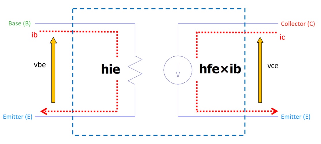
hie: input resistance
hfe: current gain
The section enclosed by the blue dotted line represents the equivalent circuit of the transistor.
Here’s why it can be drawn this way: when a base current ib flows into the transistor,
a collector current ic flows between the collector and emitter terminals.
The base current ib and the collector current ic have the following relationship:
ic = hfe × ib
Therefore, the right-hand side of the equivalent circuit is represented by hfe × ib.
On the left-hand side, hie represents the input resistance.
When the collector–emitter terminals are shorted (vce = 0 V) and a voltage vbe is applied between the base and emitter, a base current ib flows.
According to Ohm’s law, if a voltage vbe produces a current ib,
Input resistance hie = vbe / ib
Thus, the left-hand side of the equivalent circuit is hie.
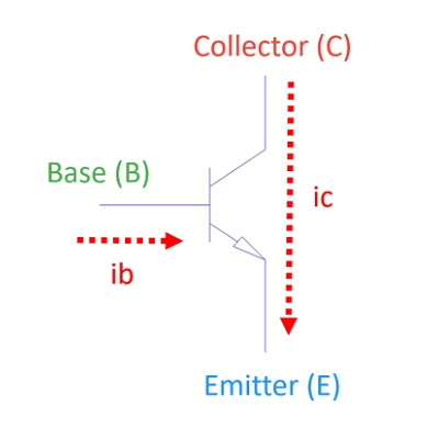
Note that the transistor discussed here refers to a bipolar transistor (NPN type).
FAQ: Why Is hfe × ib Represented as a Current Source?
Because hfe × ib is a current.
An equivalent circuit replaces a complex component with simpler electronic elements that have the same electrical characteristics.
This makes circuit analysis and calculations easier.
Since hfe × ib represents a current, it is replaced by a current source in the equivalent circuit.
The direction of the current source is downward because that matches the actual current flow in the transistor.
If it were drawn upward, it would have to be expressed as −hfe × ib, which can be confusing. Therefore, the current direction is kept consistent with the actual flow.
FAQ: I Remember Four Components in the Equivalent Circuit. Why Only Two Here?
That’s right — the complete equivalent circuit includes four parameters.
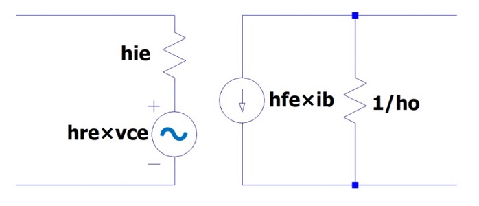
The full hybrid model of a transistor equivalent circuit is as follows.
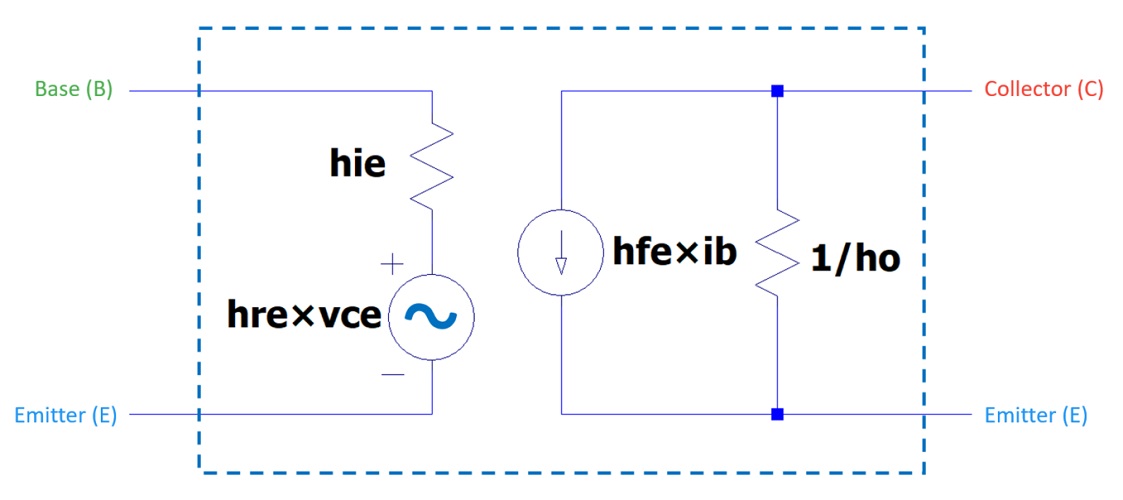
In addition to hie (input resistance) and hfe (current gain), there are two more parameters:
hre: voltage feedback ratio
hoe: reciprocal of output resistance
These are often omitted because they have little effect on circuit operation.
hre represents the amount of signal fed back from the collector–emitter side to the base–emitter side.
In most cases, the signal travels from left to right (input to output), so hre is nearly zero and can be ignored.
The term hoe represents the reciprocal of the output resistance, expressed as:
hoe = ic / vce
According to Ohm’s law, resistance = voltage / current, so the reciprocal of resistance = current / voltage.
For practical circuits, hoe is extremely small (for example, 1 µS), so 1/hoe = 1 MΩ.
If the output side of the transistor is connected to a resistor of about 1 kΩ, the total combined resistance becomes approximately the same as 1 kΩ, meaning hoe has almost no influence.
Therefore, hoe can also be omitted when drawing simplified equivalent circuits.
How to Create the Equivalent Circuit in a Transistor Amplifier
Let’s learn how to draw the small-signal equivalent circuit using the following transistor amplifier as an example.
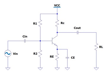
There are two basic steps to create an equivalent circuit:
- Short the capacitors.
- Connect the power supply to ground.
Let’s go through each step.
1. Short the Capacitors
When you short the capacitors, the circuit becomes as follows:
Cin is shorted → the input signal Vin is directly connected to the transistor’s base (B).
Cout is shorted → the transistor’s emitter (E) is connected to the load resistor RL.
CE is shorted → the transistor’s collector (C) is connected to ground (GND).
Note: Since capacitor CE is in parallel with resistor RE, the resistor has no effect in the equivalent circuit.
The reason capacitors can be shorted is that the small-signal equivalent circuit represents an AC signal.
DC signals cannot pass through capacitors, but AC signals can.
2. Connect the Power Supply to Ground
When you connect the power supply to ground, the circuit changes as follows:
R1 is connected to ground.
RC is connected to ground.
The reason for connecting the power supply to ground is the same — because the small-signal equivalent circuit considers only AC signals.
In AC analysis, constant DC voltages (such as 3.3 V or 5.0 V) are treated as 0 V since they do not change over time.
Therefore, the power supply is represented as ground (0 V) in the equivalent circuit.
3. Equivalent Circuit of the Transistor Amplifier
By applying the steps above, we can draw the equivalent circuit of the transistor amplifier as shown below.
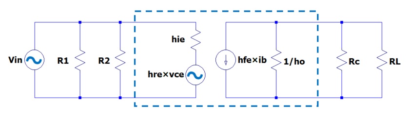
The blue dashed section represents the transistor portion within the amplifier.
Let’s Try It Out!
Now, let’s test what we’ve learned about equivalent circuits using a real circuit.
By measuring the circuit yourself, you’ll deepen your understanding.
Example Circuit
Here are the transistor amplifier circuit and its equivalent circuit we discussed earlier.
When you apply a small AC input voltage Vin, a larger AC output voltage appears at the collector side.
When a small AC voltage Vin is applied (input signal present)
→ A small AC current ib flows into the base.
→ The collector current ic changes approximately in proportion to hfe × ib.
→ A voltage variation appears across the collector resistor RL, producing a large AC output voltage (with an inverted phase).
When no AC voltage Vin is applied (no input signal)
→ The base current ib remains constant (only the DC bias current flows).
→ The collector current ic stays unchanged.
→ The voltage across the collector resistor RL remains fixed, and no AC output voltage appears.
By observing the difference between these two cases — with and without input —
you can clearly see how the current source in the equivalent circuit works in practice.
Components You’ll Need
Here are the components you’ll need to build the transistor amplifier circuit on a breadboard.
Let’s verify the “current amplification mechanism” you learned in the equivalent circuit by measuring it in a real circuit.
- NPN Transistor: 2N3904
-
A classic small-signal transistor, ideal for amplification experiments.
By observing the relationship between the base current and collector current, you can experience how the hfe × ib operation works in the equivalent circuit. - Resistor Set
-
Used as base and collector resistors.
1/4W types are sufficient, but for circuits with higher current, use 1/2W or larger for safety. - Electrolytic Capacitor Set
-
Used for input/output coupling and emitter bypassing.
You can experience the concept of “shorting capacitors” from the equivalent circuit in an actual amplifier circuit. - Breadboard (830 holes)
-
No soldering is required, and you can easily build the amplifier circuit.
It’s perfect for experiments to check how resistor values and bias conditions affect the circuit compared to the equivalent model. - Jumper Wire Set
-
Used to connect the base, collector, and emitter terminals.
Using different wire colors helps you easily visualize each signal path. - USB 5V Breadboard Power Module
-
Plug a USB power module directly into the breadboard to easily supply 5V or 3.3V.
No external power source or extra wiring is required, making it convenient for quick experiments. - Digital Multimeter (Tester)
-
Use it to measure voltage changes and compare the amplitude of input and output signals.
Start by checking if the circuit operates correctly with the multimeter. - Function Generator (Signal Source)
-
Used to input a small AC voltage into the transistor amplifier circuit.
It can generate basic waveforms such as sine, square, and triangle waves with adjustable frequency and amplitude.
Important Notes
Transistor pin layouts vary depending on the model and manufacturer.
Also, the maximum voltage and current ratings differ by product.
Always check the datasheet before connecting components to ensure correct pin assignment and safe operation.
Useful Measurement Tools
To confirm whether “the current is really amplified by hfe” or “the circuit behaves like the equivalent model,”
you’ll need some measuring instruments.
- To easily check voltage and current: → Digital Multimeter
- To observe signal waveforms: → Oscilloscope
- To power your circuit safely with a stable source: → DC Power Supply
While a multimeter can measure voltage changes, it cannot show waveform or phase inversion.
With an oscilloscope, you can observe both input and output waveforms at the same time.
Summary
In this article, we explored the equivalent circuit of a transistor and how it helps in understanding amplifier operation.
By learning how the equivalent circuit represents the relationship between currents and voltages, you can grasp the behavior of amplification more accurately.
In particular, understanding why hfe × ib is expressed as a current source and how capacitors are treated as shorts in AC analysis will be valuable when analyzing future circuits.
Related Articles
Bonus: Understanding Equivalent Circuits Helps You Read Schematics
An equivalent circuit is a simplified model that represents the internal behavior of a transistor using basic components.
When reading an actual circuit diagram, imagining how it can be replaced with current sources and resistors helps you intuitively understand how the signal flows.
For example, when you see a resistor connected to the collector in an amplifier circuit, you’ll realize that this is where current is being converted into voltage.
Likewise, when you notice an emitter resistor, you can recognize that it’s stabilizing the operating point through negative feedback.
In this way, once you understand the concept of equivalent circuits, what used to look like just lines and symbols on a schematic will start to appear as a map of signal flow.
The ability to “read” a circuit is one of the most important skills for anyone designing electronic systems.
Try applying what you’ve learned about equivalent circuits as you look through real circuit diagrams — it will transform the way you see them.