- What is a MOSFET? How is it different from a Power MOSFET?
- How do you pronounce MOSFET?
- How can you read and remember MOSFET circuit symbols?
This article answers these questions.
I’ve been working as an electronic circuit designer for about 10 years.
“I understand transistors, but I don’t quite get MOSFETs…”
I used to feel the same way.
Now, after years of designing circuits using MOSFETs professionally, I can clearly explain how they work and how to read their symbols.
I’ll share that knowledge here, based on real design experience.
By the end of this article, you’ll understand what MOSFETs are and how to read their circuit symbols.
This guide takes only about 3 minutes to read—so let’s get started!
What Is a MOSFET? (Including How to Pronounce It)
MOSFET as a Type of Transistor
A MOSFET is one type of transistor.
In general, transistors can be classified into the following types:
- Bipolar Junction Transistor (BJT)
- Field Effect Transistor (FET)
- Metal–Oxide–Semiconductor Field-Effect Transistor (MOSFET) ← this one
- Junction Field-Effect Transistor (JFET)
- Insulated Gate Bipolar Transistor (IGBT)
MOSFETs belong to the category of field-effect transistors.
“Field Effect Transistor” is abbreviated as FET.
The term MOSFET comes from the three-layer structure it’s made of:
Metal, Oxide, and Semiconductor.
Taking the initials gives us MOS.
The oxide layer insulates the metal gate from the semiconductor.
The word “insulated gate” in “insulated gate field-effect transistor” refers to the fact that an oxide layer is placed between the metal gate and the semiconductor to provide insulation.
How to Pronounce MOSFET
MOSFET is usually pronounced as:
“moss-fet”
“moss transistor”
or simply “FET”
Among engineers, “moss-fet” is the most common pronunciation.
In casual conversation, when it’s obvious that you’re talking about MOSFETs, people often just say “FET”.
About MOSFET Model Numbers
When it comes to MOSFET model numbers, you don’t have to worry too much about them.
MOSFETs come in two main types: N-channel and P-channel.
In Japanese components, these are often labeled as follows:
2SK → N-channel MOSFET
2SJ → P-channel MOSFET
For example:
N-channel MOSFETs include Toshiba’s 2SK2232 and 2SK4017.
P-channel MOSFETs include Toshiba’s 2SJ334.
However, these models are discontinued or scheduled to be discontinued.
Toshiba now recommends TK30A06N1 as a successor to the 2SK2232.
Today, many manufacturers produce MOSFETs, and each company uses its own numbering rules.
For example:
ROHM: R6015ENZ
Panasonic: FC6546010R
KEC: KF10N60F
As you can see, there’s no universal standard for MOSFET part numbers.
So, in most cases, you don’t need to focus too much on the model number—just choose a MOSFET that fits your circuit’s specifications.
What Is a Power MOSFET? (Difference from a Standard MOSFET)
A Power MOSFET is a device that contains thousands to hundreds of thousands of individual MOSFETs integrated inside a single chip.
Each MOSFET inside the chip has the same specifications and can carry the same amount of current.
For example, even if one MOSFET can only handle around 10 mA, combining 1,000 of them in parallel allows the device to handle about 10 A in total.
Therefore, it is called a power device capable of handling large currents — hence the name “Power MOSFET.”
Depending on the model, Power MOSFETs can typically handle around 10 to 300 W of power, based on practical design experience.
FAQ: What Does “SiC” Mean in a MOSFET?
“SiC” stands for Silicon Carbide, which is one of the semiconductor materials used to build MOSFETs.
Most MOSFETs are made of silicon (Si), the standard material used in semiconductor devices.
However, MOSFET performance has been continuously improving, and in recent years,
SiC (Silicon Carbide) has been used to achieve higher voltage resistance and lower on-resistance.
That said, when designing electronic circuits,
you usually don’t need to worry about the semiconductor material itself.
When selecting a MOSFET for your design,
focus on the electrical characteristics in the datasheet to ensure it meets your circuit requirements.
MOSFET Circuit Symbols
Four Types of MOSFET Symbols
As mentioned earlier, MOSFETs come in two main types: N-channel and P-channel.
Each of these can be further divided into Enhancement type and Depletion type.
Therefore, there are four types of MOSFET circuit symbols in total.
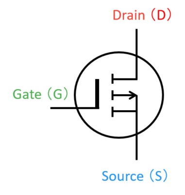
[N-Channel MOSFET – Enhancement Type]

The arrow points from P to N.
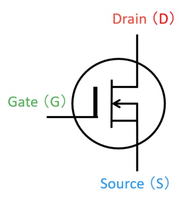
[P-Channel MOSFET – Enhancement Type]
The arrow points in the opposite direction to the N-channel type.
[N-Channel MOSFET – Depletion Type]
The solid channel line indicates conduction at VGS = 0.
[P-Channel MOSFET – Depletion Type]

The arrow direction is reversed compared to the N-channel type.
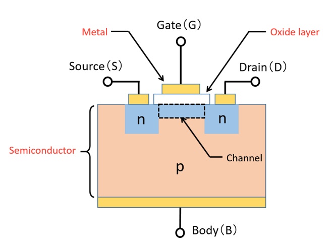
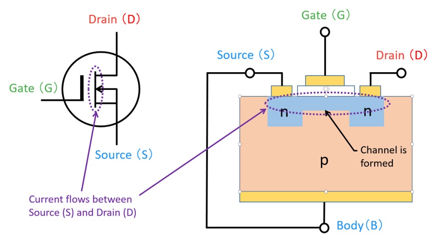
A MOSFET consists of three terminals: Gate (G), Drain (D), and Source (S).
These are the three terminals you usually see in a circuit diagram.
However, in reality, MOSFETs actually have four terminals. Let’s take a closer look at why.
Actually, There Are Four Terminals
In addition to the Gate (G), Drain (D), and Source (S), MOSFETs also have a fourth terminal called the Body (B).
Since this is true for all MOSFET types, let’s use the N-channel enhancement type as an example.
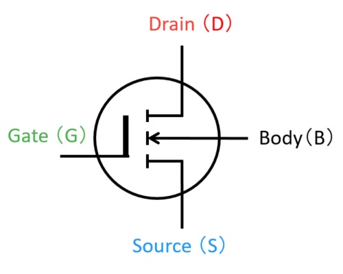
The fourth terminal is the Body (B).
The above diagram shows the four-terminal version of the circuit symbol.
The reason there are four terminals is that the MOSFET’s internal structure is physically made that way.
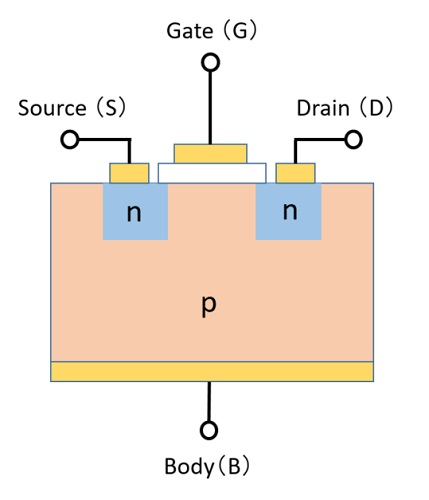
The Body (B) is connected to the substrate.
Then, why do most circuit symbols and physical components only show three terminals?
This is because the Source and Body terminals are connected internally inside the package.
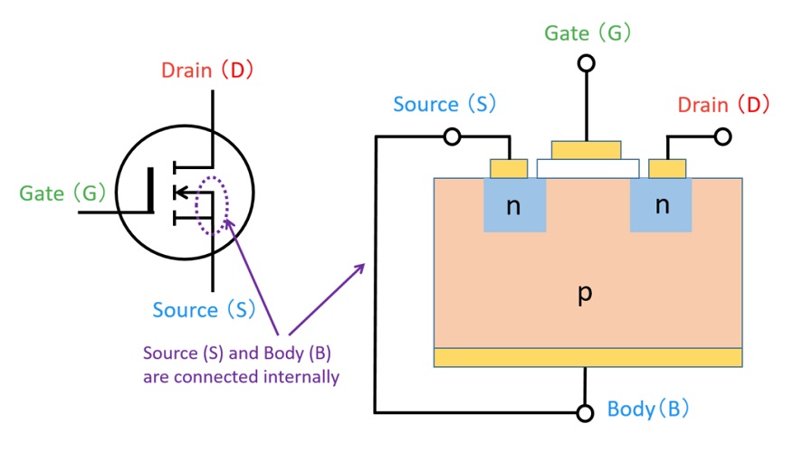
Therefore, in most cases, MOSFETs are used as three-terminal devices.
The Body (B) terminal is also known as the bulk or back gate.
How to Remember MOSFET Circuit Symbols
It can be difficult to memorize all four MOSFET symbols,
but you can easily distinguish them by focusing on two key differences:
- Enhancement type vs. Depletion type: dotted vs. solid line
- N-channel vs. P-channel: arrow direction
Let’s look at each difference in detail.
Enhancement vs. Depletion Type: Dotted or Solid Line
[Enhancement Type – N-Channel MOSFET]
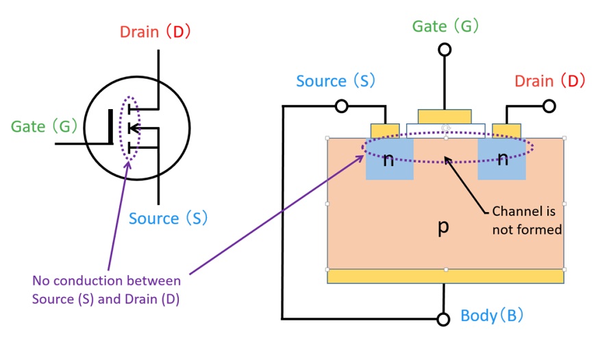
when VGS = 0, the channel is not formed,
so no current flows between Source and Drain.
[Depletion Type – N-Channel MOSFET]
when VGS = 0, the channel already exists,
so current can flow between Source and Drain.
As shown above:
Enhancement type → dotted line
Depletion type → solid line
The reason is simple:
For an Enhancement type MOSFET,
when VGS = 0 (no voltage applied to the gate), the channel is not formed,
so current does not flow between the source and drain — that’s why it’s shown as a dotted line.
For a Depletion type MOSFET,
when VGS = 0, the channel is already formed,
so current flows between the source and drain — that’s why it’s shown as a solid line.
In short:
Enhancement type → dotted line (no conduction at VGS=0)
Depletion type → solid line (conducts at VGS=0)
N-Channel vs. P-Channel: Arrow Direction
[Depletion Type – N-Channel MOSFET]
the arrow points from the P-type semiconductor to the N-type channel,
indicating the P→N direction.
[Depletion Type – P-Channel MOSFET]
the arrow direction is reversed,
pointing from the P-type channel to the N-type region.
The direction of the arrow follows the rule:
The arrow points from P → N.
This is because the letters “P” and “N” represent:
P = Positive (+)
N = Negative (−)
In other words, the arrow points from positive to negative — from P to N.
To put it simply:
The arrow always points from P to N.
If you’d like to learn more about MOSFET structure and how it works,
see MOSFET Structure and Working Principle Explained (N-channel and P-channel).
Let’s Try It Yourself!
Just looking at MOSFET symbols might not give you a clear picture of how they actually work.
So, let’s build a simple circuit and see the operation in action!
Example Circuit
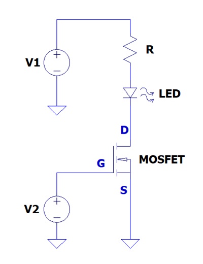
Using an N-channel enhancement-type MOSFET makes it easy to understand the relationship between the circuit symbol and real-world operation.
When you apply or remove voltage to the Gate (G),
the current flow between the Drain (D) and Source (S) changes, and the LED turns ON or OFF accordingly.
When voltage is applied to the Gate (G):
→ A channel is formed
→ The Drain–Source path conducts
→ Current flows from Drain (D) to Source (S)
→ The LED lights up
When the Gate (G) is at 0V:
→ The channel is not formed
→ The Drain–Source path does not conduct
→ No current flows from Drain (D) to Source (S)
→ The LED stays OFF
This experiment helps you visualize how the Gate, Drain, and Source work together in an actual MOSFET circuit.
Components You’ll Need
- MOSFET 2N7000
-
An enhancement-type N-channel MOSFET ideal for LED switching experiments.
It’s a globally used beginner-friendly model and easy to handle for first-time users. - Resistor Set
-
Use resistors between 330 Ω and 1 kΩ for LED circuits.
For basic experiments, 1/4 W is sufficient, but for higher current, use 1/2 W or above for safety. - LED Set
-
LEDs light up when current flows, making it easy to confirm the switching operation.
Having multiple colors like red and green helps with comparison and visual testing. - Breadboard (830 holes)
-
A solderless breadboard lets you easily build circuits without soldering.
It’s perfect for quick prototyping and learning basic electronics. - Jumper Wire Set
-
Use these wires to connect components on the breadboard.
Having male–male, male–female, and female–female types will make your setup more flexible. - USB 5V Breadboard Power Module
-
This module provides stable 5V or 3.3V power directly to the breadboard.
It’s convenient for small circuit experiments and safe for beginners. - Digital Multimeter (Tester)
-
Measure the gate voltage and drain current to observe how the MOSFET switches.
Even an entry-level multimeter works well for this experiment.
Important Notes
MOSFET pin configurations may vary depending on the manufacturer and model.
Also, the maximum voltage and current ratings differ by product.
Always check the datasheet for pin layout and ratings before building your circuit.
Useful Tools for Measurement
If you want to check “Is it really switching like a transistor?” or “How much current is flowing?”,
try using measurement tools.
- To easily check voltage and current: → Digital Multimeter
- To observe signal waveforms: → Oscilloscope
- To power your circuit safely with a stable source: → DC Power Supply
By using measurement tools,
you can gain a deeper understanding of how the circuit symbol represents actual MOSFET behavior.
Summary
In this article, we’ve explained the basics of MOSFETs.
MOSFETs are widely used in motor driver circuits and logic circuits,
so it’s worth understanding how they work.
We hope this guide helps you gain a clearer understanding of MOSFETs and their operation.